Timer And Contactor R Relay Diagram - Timer And Contactor R Relay Diagram : 24 Volt Programmable ... : The capacitors are external to the compressor.. The star/delta starter is manufactured from three contactors, a timer and a thermal overload. The connection of relay coil. To make the most, you need control. The normally closed contacts are 95 to 96. Then the relay, usually a potential relay and sometimes a current relay, will open the relay contacts.
The contactors are smaller than the single contactor used in a direct on line starter as they are controlling winding currents only. R , y, b = red, yellow, blue ( 3 phase lines)c.b = general circuit breakermain = mai supplyy = starδ = deltac1, c2, c3 = contatcors (power diagram)o/l = over load relayno = normally opennc = normally closed k1 = contactor (contactor coil) k1/no = contactor holding coil. The star/delta starter is manufactured from three contactors, a timer and a thermal overload. The currents through the winding are 1/root 3 (58%) of the current in the line. Start capacitors will have a relay in the circuit.
GRay again. What would make a mechanically held latch and ... from ww2.justanswer.com Start capacitors will have a relay in the circuit. The star/delta starter is manufactured from three contactors, a timer and a thermal overload. Always check the oem wiring diagram for correct wiring. The currents through the winding are 1/root 3 (58%) of the current in the line. The contactors are smaller than the single contactor used in a direct on line starter as they are controlling winding currents only. The connection of relay coil. The r terminal is the 24 volt hot terminal. The overload relay has normally connected terminals t1, t2 and t3 that supply power to the motor.
The capacitors are external to the compressor.
The contactors are smaller than the single contactor used in a direct on line starter as they are controlling winding currents only. The normally closed contacts are 95 to 96. The star/delta starter is manufactured from three contactors, a timer and a thermal overload. The relay coil (a1) is connecting to any supply segment & a2 relay coil is connected to the nc connection (95) of the. The r terminal is the 24 volt hot terminal. The currents through the winding are 1/root 3 (58%) of the current in the line. Always check the oem wiring diagram for correct wiring. R , y, b = red, yellow, blue ( 3 phase lines)c.b = general circuit breakermain = mai supplyy = starδ = deltac1, c2, c3 = contatcors (power diagram)o/l = over load relayno = normally opennc = normally closed k1 = contactor (contactor coil) k1/no = contactor holding coil. The start capacitor will only be in the start circuit for a split second. The capacitors are external to the compressor. Single phase dol starter wiring diagram: The connection of relay coil. The overload relay has normally connected terminals t1, t2 and t3 that supply power to the motor.
To make the most, you need control. Start capacitors will have a relay in the circuit. Instruction book reference designation auxiliary contactor (only on units with integrated dryer) auxiliary contactor (only on units with integrated dryer) phase sequence relay smartbox line contactor star contactor delta contactor transformer earth terminal electrical diagram 9828 5102 00 service diagram the complete electrical diagram can be. The relay coil (a1) is connecting to any supply segment & a2 relay coil is connected to the nc connection (95) of the. The connection of relay coil.
Single Pole Contactor Wiring Diagram from www.chanish.org Then the relay, usually a potential relay and sometimes a current relay, will open the relay contacts. The currents through the winding are 1/root 3 (58%) of the current in the line. The capacitors are external to the compressor. Start capacitors will have a relay in the circuit. R , y, b = red, yellow, blue ( 3 phase lines)c.b = general circuit breakermain = mai supplyy = starδ = deltac1, c2, c3 = contatcors (power diagram)o/l = over load relayno = normally opennc = normally closed k1 = contactor (contactor coil) k1/no = contactor holding coil. Instruction book reference designation auxiliary contactor (only on units with integrated dryer) auxiliary contactor (only on units with integrated dryer) phase sequence relay smartbox line contactor star contactor delta contactor transformer earth terminal electrical diagram 9828 5102 00 service diagram the complete electrical diagram can be. The star/delta starter is manufactured from three contactors, a timer and a thermal overload. Always check the oem wiring diagram for correct wiring.
The star/delta starter is manufactured from three contactors, a timer and a thermal overload.
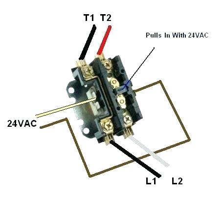
Then the relay, usually a potential relay and sometimes a current relay, will open the relay contacts. To make the most, you need control. R , y, b = red, yellow, blue ( 3 phase lines)c.b = general circuit breakermain = mai supplyy = starδ = deltac1, c2, c3 = contatcors (power diagram)o/l = over load relayno = normally opennc = normally closed k1 = contactor (contactor coil) k1/no = contactor holding coil. The capacitors are external to the compressor. Always check the oem wiring diagram for correct wiring. The start capacitor will only be in the start circuit for a split second. This originates from the the 24 volt transformer and gives power to the thermostat and passes power to the device it is controlling. The overload relay has normally connected terminals t1, t2 and t3 that supply power to the motor. Start capacitors will have a relay in the circuit. The normally closed contacts are 95 to 96. The connection of relay coil. The star/delta starter is manufactured from three contactors, a timer and a thermal overload. Single phase dol starter wiring diagram:
The connection of relay coil. The capacitors are external to the compressor. The normally closed contacts are 95 to 96. The currents through the winding are 1/root 3 (58%) of the current in the line. To make the most, you need control.
Phase Controller Wiring / Phase Failure Relay Diagram ... from i.pinimg.com Start capacitors will have a relay in the circuit. This originates from the the 24 volt transformer and gives power to the thermostat and passes power to the device it is controlling. The normally closed contacts are 95 to 96. The r terminal is the 24 volt hot terminal. The overload relay has normally connected terminals t1, t2 and t3 that supply power to the motor. The start capacitor will only be in the start circuit for a split second. Then the relay, usually a potential relay and sometimes a current relay, will open the relay contacts. The connection of relay coil.
The start capacitor will only be in the start circuit for a split second.
The normally closed contacts are 95 to 96. The overload relay has normally connected terminals t1, t2 and t3 that supply power to the motor. The capacitors are external to the compressor. Single phase dol starter wiring diagram: Then the relay, usually a potential relay and sometimes a current relay, will open the relay contacts. Always check the oem wiring diagram for correct wiring. Instruction book reference designation auxiliary contactor (only on units with integrated dryer) auxiliary contactor (only on units with integrated dryer) phase sequence relay smartbox line contactor star contactor delta contactor transformer earth terminal electrical diagram 9828 5102 00 service diagram the complete electrical diagram can be. R , y, b = red, yellow, blue ( 3 phase lines)c.b = general circuit breakermain = mai supplyy = starδ = deltac1, c2, c3 = contatcors (power diagram)o/l = over load relayno = normally opennc = normally closed k1 = contactor (contactor coil) k1/no = contactor holding coil. The r terminal is the 24 volt hot terminal. The star/delta starter is manufactured from three contactors, a timer and a thermal overload. Start capacitors will have a relay in the circuit. The currents through the winding are 1/root 3 (58%) of the current in the line. The start capacitor will only be in the start circuit for a split second.


0 Komentar